What is an FDM Printer?
Fused Deposition Modeling (FDM) printers build 3D objects by precisely controlling the flow of a thin strand of molten plastic from a moving nozzle. They are the most common type of 3D printer. Root Access Hackerspace has state-of-the-art FDM printers that are fast, reliable, and capable of producing high-quality prints. Our printers support multi-color and multi-material prints.
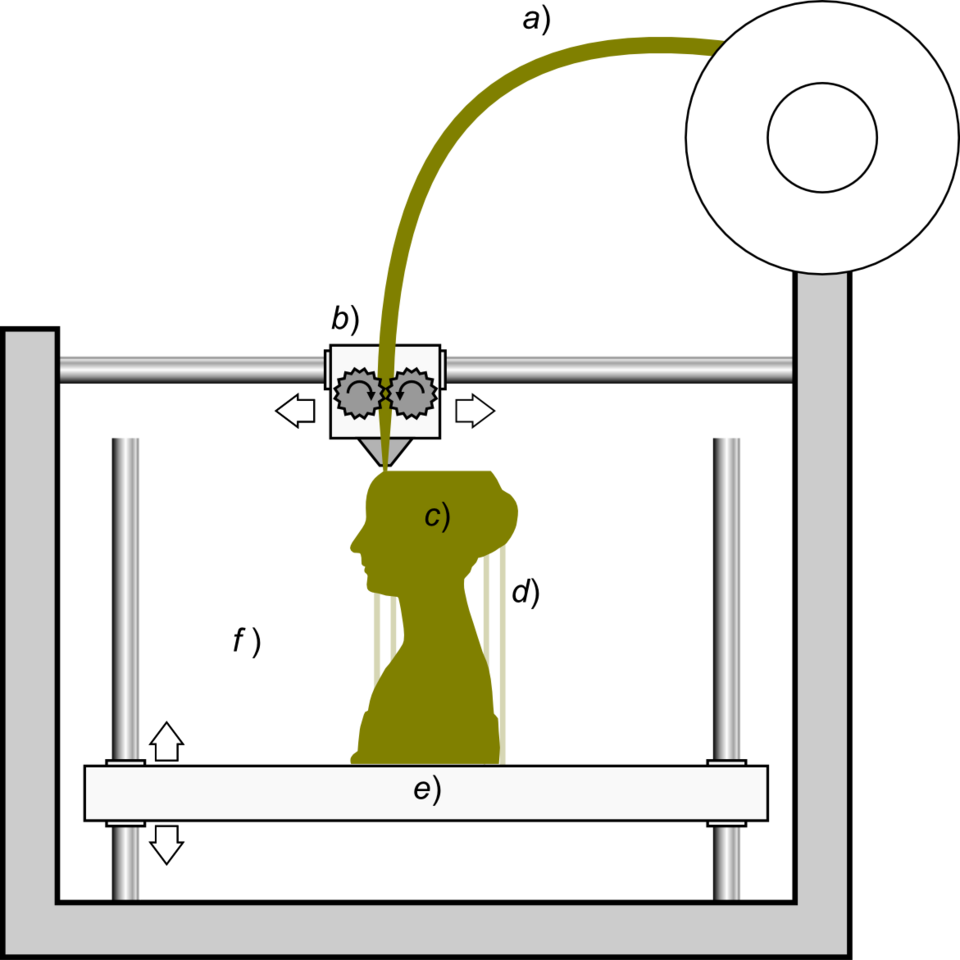
Here is how an FDM printer works. See figure below:
a) A long, flexible strand of plastic filament is fed into the printer from a spool.
b) The moving printhead grips the filament and forces it through a hot nozzle to melt it.
c) The printed object is built up one layer at a time.
d) The printer also lays down support material where needed to support overhanging portions of the printed object. These can be removed after the print is complete.
e) The print bed acts as a foundation for the printed object as it is being built up. In the printer shown in the diagram, the bed moves up and down and the printhead moves side to side and forward and back.
Scopigno R., Cignoni P., Pietroni N., Callieri M., Dellepiane M. (2017). "Digital Fabrication Techniques for Cultural Heritage: A Survey". Computer Graphics Forum 36 (1): 6–21.
Access, Materials, and Payment
The only requirements to use our FDM 3D printers are:
- Having a tool access-granting membership tier.
- Following our Standard Operating Procedures (SOP's) for our printers.
We have a monthly 3D printing class, but it is not required to use the FDM 3D printers.
Members are welcome to use the space's filament collection, or to bring their own filament.
If you use filament from the space, please make a donation to cover the cost of replacing what you used. Details for how to calculate material costs are provided below in the SOP's section.
Our filament spools are stored in a rolling organizer under the 3D printer shelf. After a print is finished, spools should be put into a clear resealable bag and placed in the proper slot in the organizer. If there is room for it, members are welcome to donate filament spools to the organizer. If you want to reserve a spool you have purchased for your own use, clearly mark it and store it in your locker.
Recommended Software
- OrcaSlicer
- Our recommended software. It is free and open source and can be used with all of our FDM printers.
- After you click the link above, you can find the OrcaSlicer download for your OS at the bottom of the page under "Assets."
- Be sure to download OrcaSlicer ONLY from this github page, which is their official source. Avoid "-orcaslicer.net-", "-orcaslicer.co-" and "-orca-slicer.com-" as these are unofficial and potentially malicious.
Our Printers: Overview
Here is our current roster:
| Model | Supports multi-color? | Build Volume |
|---|---|---|
| Bambu A1 Mini | no | 180 x 180 x 180 mm |
| Bambu P1S | yes | 256 x 256 x 256 mm |
| Bambu H2C | yes | 320 x 320 x 320 mm |
FDM Printer Standard Operating Procedures (SOP's)
1. Setting Up a Print Job in Orcaslicer
- Get an STL file of your model. 3D models are typically shared online as STL files, and most 3D modeling programs can export a model as an STL file.
- Open Orcaslicer on your laptop or on one of the computers at the space. See the Recommended Software section above for instructions on how to download and install Orcaslicer.
- Press the New Project button. This will open the print setup dialog.
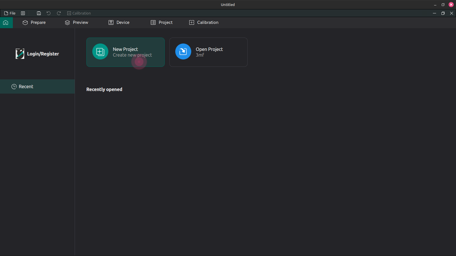
- Click the printer selection dropdown list. This will show a list of the specific 3D printers that have already been added as a preset.
If you do not see the desired printer in the list, choose "Select/Remove Printers(system presets)" This will bring up a dialog where you can find the printer by manufacturer and model. All of our printers have 0.4 mm nozzles.
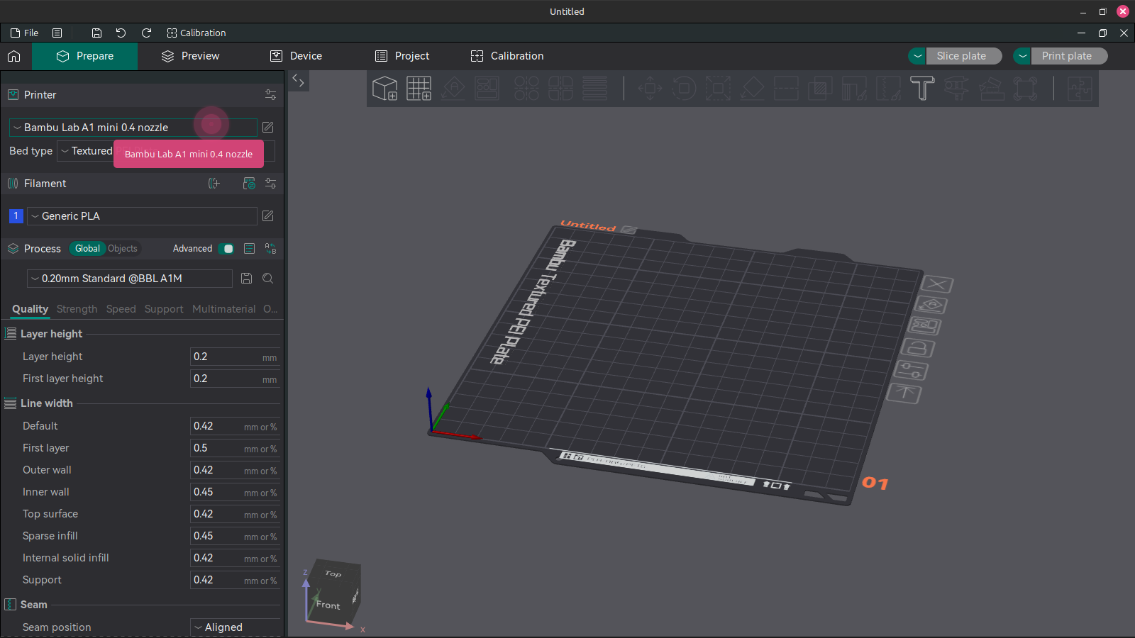
Click the desired printer in the selection dropdown list. You should see the size and shape of the print bed in the viewport change to reflect that of the physical 3D printer print bed.
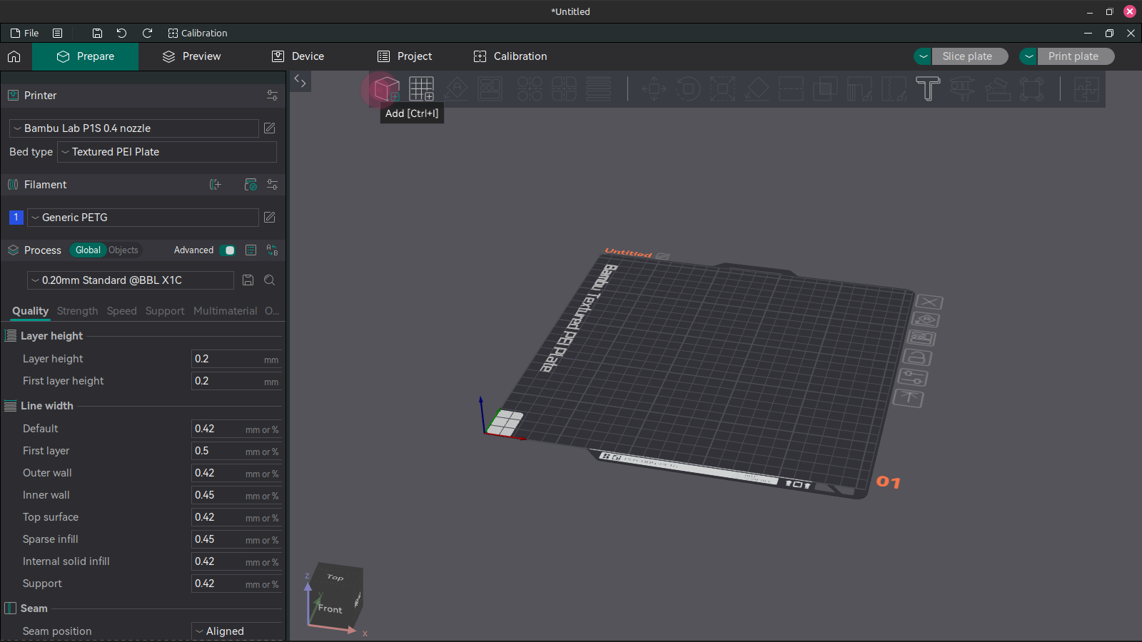
Click the Add button to add your STL file(s) to the print job. This will bring up a file import dialog. If you downloaded a model from Thingiverse, you will need to extract the downloaded zip folder.
- Adjust the viewport camera to inspect your model throughout the rest of these steps.
- left click and drag to rotate the camera
- right click or click scroll wheel and drag to pan the camera
- use the scroll wheel to zoom
- Optional: Select an imported object by left clicking it. Use the Move, Rotate, Scale, and Lay On Face tools to adjust the size, orientation, and position of your model as needed. These four tools are grouped together in the middle of the tool bar.
- Move Tool: Click on the red, green, or blue cones to move the object along the corresponding axis. You can also move an object by clicking and dragging on it with no tool selected.
- Rotate Tool: Enter the angle you want the model to be rotated about an axis and hit enter to execute the rotation, or click and drag on the green, red, or blue cubes to rotate the model about the corresponding axis.
- Scale Tool: If you know in advance how wide, long, or tall you want the final object to be, you can enter that value in millimeters in the "Size" row of the scale tool dialog box. Alternatively, you can enter a percentage value in the "Scale" row to change the object's size. For example if you want to double the object's size you would enter 200 in any of the x, y, or z fields and hit enter to apply the scale. If you uncheck the "Uniform Scale" box, you can stretch or compress your model along any of the three axes. In the viewport, you can also click and drag on the colored cubes to perform a scale change. For a uniform scale (no stretching or compressing), click and drag the corner teal cubes. Clicking and dragging on the red, green, or blue cubes will stretch or compress the model along the corresponding axis.
- Lay Flat Tool: If you want to ensure that a specific flat surface on your object sits flat on the print bed, click the Lay Flat tool. Translucent white patches will apear on and around your model. Click on the one that matches the surface you want to lay flat to execute.
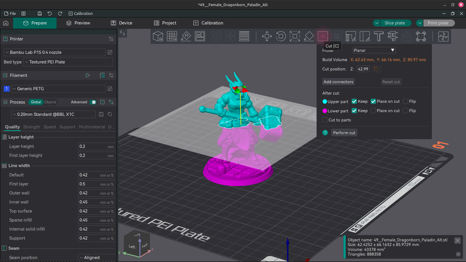
- Optional: If needed, use the Cut tool to break a large model up into multiple pieces or create a flat surface for the object's base layer. A model does not strictly need to have a flat surface where it meets the build plate, but without a flat surface it will need extensive support material underneath.
- Enter a value in the "Cut position: Z:" field to precisely set the height of the cutting plane. You can also rotate and move the cutting plane by clicking and dragging on the red and green cones and gray sphere in the viewport window.
- If you are breaking up a large model into multiple small objects, you can create connecting pins and holes by pressing the "Add connectors" button.
- The "After cut" section of the Cut dialog box allows you to control which sides of the cut are preserved and how they are oriented.
- When you are satisfied with the Cut settings, press the "Perform cut" button.
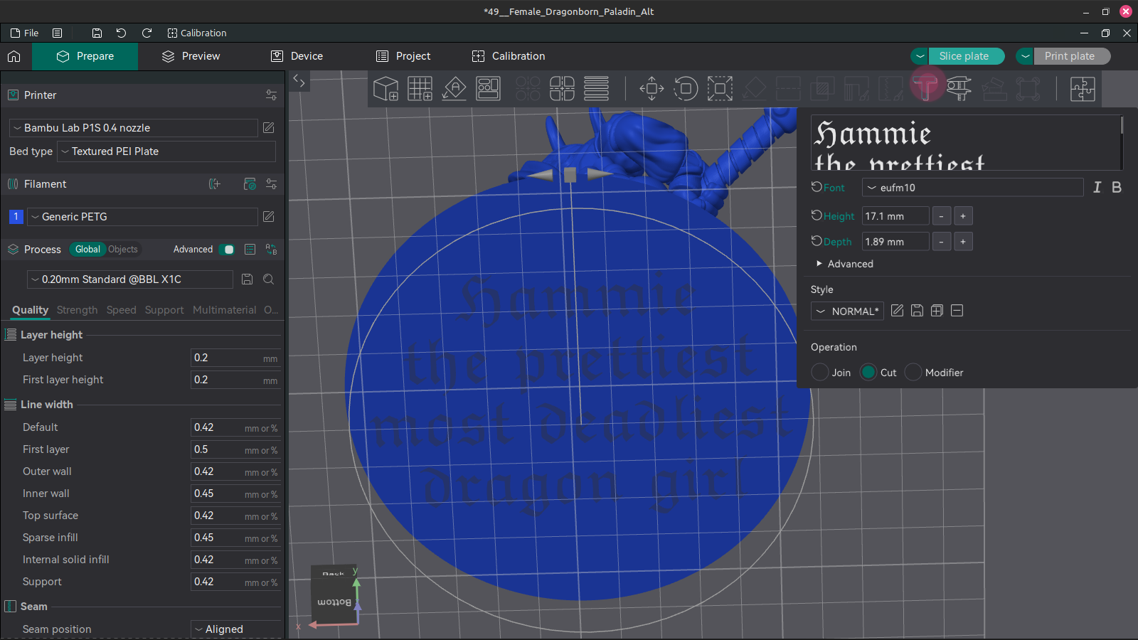
- Optional: Use the Emboss tool to add raised text or engraved text onto your model.
- Select your model by left clicking it before clicking the Emboss tool.
- Choose a font and set the size of your lettering with the height and depth options.
- Text can be moved by clicking and dragging on it in the viewport window. You can also move text by exiting the emboss tool dialog and using the move and rotate tools on the text.
- Under the Advanced options in the Emboss tool dialog, check the "Use surface" box to project the text onto the surface of your model.
- Also under the Advanced options, you can use the "Set text to face camera" button to align the text to whatever angle the current camera view is.
- At the bottom of the Emboss tool dialog box, under "Operation" chooose "Join" for raised text or "Cut" for engraved text.
- Note that you won't see the text actually cut into the surface of the model until later in the print setup process. For now the text will just appear in a different color from your model.
Print Station 2: Bambu P1S
Workflow for Bambu P1S
- Load desired colors / materials into AMS as shown in the video below. Note which slot you put each color in; they are numbered 1-4 from left to right.
How To Load Filament Into AMS:
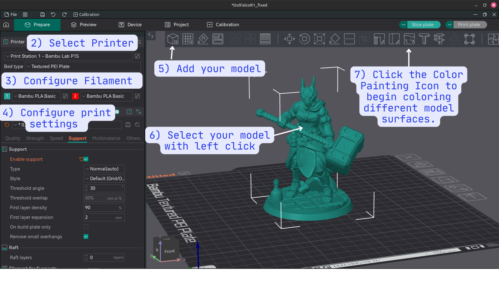
In Orcaslicer, select or set up a printer profile for the Bambu P1S. If you're at Root Access we recommend using PC Workstation 1 where Orcaslicer is already installed and profiles are set up for all four FDM printers.
Configure filament in Orcaslicer. Click the "+" icon to add another filament spool. The number displayed next to each spool corresponds with the slot number in the Bambu Lab AMS (spool holder). You can change the color icon for each spool in orcaslicer to something closer to the actual color loaded in the AMS to help you keep track of which parts of your print will be which color.
Configure print settings such as infill, wall count, adhesion, and support.
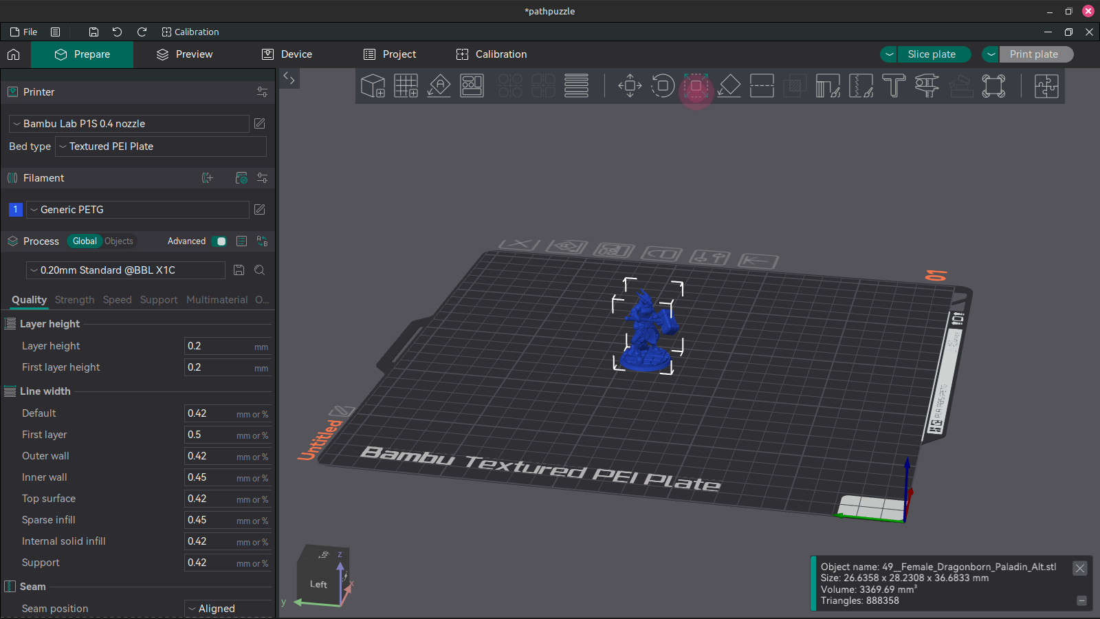
Add your model by clicking the icon shown in the figure below.
Select your model by left clicking it.
Click the icon shown below to begin painting your model.
- Use the painting interface to define which surfaces of your model will be printed with which filament spool.
- Here is a brief description of each brush's function. See image below to find the corresponding icon for each brush.
- A. Circle Brush: A simple freehand brush with adjustable size. Applies to only the single surface touched by the mouse pointer.
- B. Sphere Brush: Another freehand brush that marks any part of the model within the boundary of an adjustable sphere centered at mouse pointer.
- C. Triangle Fill: 3D models are composed of a mesh of small flat triangles. This brush targets them individually.
- D. Height Range: This brush allows you to specify all surfaces within a height range to take on a specific color.
- E. Area Fill: A smart brush that allows you to select and color different areas of your model. To save time, try using this brush first before using the freehand brushes.
- F. Gap Fill: This is not a brush but a tool that applies to your whole model. Adjust the gap size to allow Orcaslicer to automatically detect and fill in small areas between larger areas. This will result in a cleaner look and reduce unnecessary color switching at printing time.
- When you are satisfied with the coloring of your model and all other print settings, click Slice Plate and Orcaslicer will process your model. Look over the sliced model and inspect the supports and any bed adhesion features you have added. Adjust these settings if needed then slice again. Note the cost of the model is displayed among other information after slicing is complete. Remember, materials are not included in your membership so if you used filament from the space please make a donation to cover the cost of the print. To help keep the print area self-sufficient, we ask that you round up to the nearest dollar. In this example I would round the calculated $7.12 up to $8.00. See figure below.
Select "Export G-Code file" from the dropdown menu to the right of the "Slice Plate" button. Export the G-code file to a micro SD card. Use one of several micro SD to USB adapters available in the 3D printing utility area next to Print Station 1. Note the name of the G-code file so you can find it in step 11. Be sure to unmount the micro SD card before removing it to prevent file corruption.
At Print Station 1, insert the micro SD card into its slot on the machine. See figure below. Depending on the shape of your print's footprint, you may want to apply a thin layer of glue from a glue stick to the print bed. Use the directional arrow keys to navigate to the folder icon on the LCD screen. It will take a few seconds for the printer to load the files on the SD card, so be patient. Find your g-code file in the list, hit OK to select then OK again to print.
- The printer will perform a self-calibration and preparation sequence before it starts on your print. It will make several strange noises; this is normal. It's a good idea to stick around to monitor the first few layers at least for any problems such as poor extrusion or parts of the print not sticking to the bed. Once you are satisfied that the print is off to a good start, you can leave it and come back after it's finished. When it's done, allow time for it to cool down, then remove the flexible build plate and bend it to remove the finished print.
And here is the finished model. The supports for the figure's hammer came unstuck from the print bed causing the lower half to separate from the rest. To correct this for a future print I can make it so the supports are on a raft with the main print. This illustrates the importance of checking the auto-generated supports in orcaslicer before printing. A failed print doesn't have to be a complete loss though; for example here I've used hot glue and air-dry clay to turn the mishap into a new feature.
Other Standart Operating Procedures
Drying Filament
It's important to make sure your filament is dry before printing, as filament that has absorbed moisture can be very brittle and will print poorly. There is a filament dryer at the space and here are some times and temperatures to use for various filament materials commonly used:
| Material | Temperature | Hours |
|---|---|---|
| ABS | 60°C (140°F) | 3 |
| ASA | 80°C (175°F) | 4 |
| PETG | 55°C (130°F) | 6 |
| PLA | 45°C (115°F) | 6 |
Online Resources
Guides
- Bed Leveling Guide
- 3D Printer Troubleshooting Guide - MatterHackers
- Print Quality Troubleshooting Guide - Simplify3d
- Ultimate 3D Printing Troubleshooting Guide - 3DSourced